Customer Service
Demand Confirmation
Program Confirmation
Installation and Commissioning
Use Maintenance
Applications
Download
Active service + fast service + free service + butler service + strategic service
Joint technology innovation, joint quality research, joint new product development, joint lean production, joint marketing
Technical solution: technical and quality plan confirmation
Business plan: settlement and price plan confirmation
Assembly and installation work must be carried out cautiously by trained and qualified personnel; The manufacturer is not responsible for any damage caused by improper assembly and installation;
At the stage of planning, sufficient space should be left for the reducer for future maintenance and repair work;
Always prepare suitable lifting equipment before starting assembly and installation work;
If the gear unit (motor) is equipped with a fan, there should be enough space to be able to draw in air;
The instructions on the drive nameplate match the on-site power supply;
The transmission should be intact (not damaged during transport or storage);
Confirm that the following requirements have been met:
For standard reducer: ambient temperature 0 °C ~ +40 °C
No oil, acid, harmful gases, steam, radioactive objects, etc.;
For special types: the transmission is configured according to environmental conditions;
For worm gear reducer: Cannot use reducer with self-locking function
Applying a large reverse external moment of inertia to avoid damage to the reducer;
In order to ensure good lubrication, be sure to follow the installation location specified in the order;
Be sure to pay attention to the warnings and safety signs of the gear unit (motor).
Thoroughly remove preservatives, dirt or the like from the output shaft and flange surface with commercially available solvents;
Note: Do not allow solvent to immerse into the seal lip of the oil seal, otherwise the solvent may damage the oil seal;
If the reducer is stored for more than 1 year, the service life of the lubricant in the bearing will be shortened;
If mineral or synthetic oil (CLPHC) is added and the filling is in accordance with the requirements of the installation position, the gear unit can be operated at any time in this case. However, it is still necessary to check the oil level before starting;
In some cases, the synthetic oil (CLPPG) is added, the oil level is higher, and the oil level should be corrected before starting.
The reducer (motor) can only be installed on the flat, shock-absorbing and torsion-resistant support structure according to the specified installation position; the cabinet foot and the mounting flange cannot be tightened at the same time during the installation to avoid mutual competition;
When the reducer (motor) is fixed to the foundation of its concrete using bolts or foundation blocks, there should be a suitable groove to accommodate the reducer (motor);
Please check whether the oil filling amount matches the installation position during installation. If the installation position changes, please adjust the oil amount accordingly;
Install a straight-through ventilator or open the ventilator to transport the rubber ring;
Do not hit or hit the shaft end;
The vertical installation of the motor must be shielded to prevent foreign matter or liquid intrusion (rain cover C);
When installing the junction box, point the cable entry point down.
Install and fix input and output drive parts (such as parts of the coupling, etc.) on the shaft of the reducer;
If these parts need to be preheated prior to installation, see the dimensional drawing in the coupling file for the correct mating temperature;
The misalignment of the shaft may be caused by assembly or by actual operation (such as thermal expansion, shaft deflection, insufficient rigidity of the frame, etc.);
For the alignment error of the coupling approval, please refer to the manual of the corresponding brand coupling;

The centering should be performed in two axial planes that are perpendicular to each other. You can use a ruler (radial misalignment) and a feeler gauge (angle misalignment) for centering;
Unless otherwise specified, these parts can be preheated by induction heating, or they can be preheated with a burner or in a furnace.
The solid shaft end of the working machine shall be equipped with the A-type flat key according to the first part of DIN6885 standard, and shall have a central hole on the end face conforming to DIN standard 322 DS type (threaded);
Check the hollow shaft of the reducer and the solid shaft of the working machine for damage to the shaft seat and the edge part; if necessary, repair and clean it with suitable tools;
The reducer is mounted with a nut and a screw, and the reaction force is provided by the hollow shaft of the reducer;
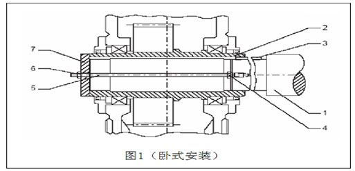
1 Working machine solid shaft 2 Reducer hollow shaft 3 Flat key 4 Nut 5 Screw 6 Nut 7 End plate
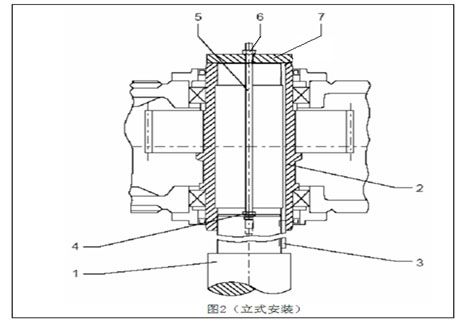
1 Working machine solid shaft 2 Reducer hollow shaft 3 Flat key 4 Nut 5 Screw 6 Nut 7 End plate
In addition to the nut and screw shown in Figures 1 and 2, other types of devices can be used, for example a set of hydraulic lifting devices can be used.
The center end of the solid shaft of the working machine shall be equipped with a central hole conforming to DIN standard 322 DS type (threaded);
Installation with integral bushings;
The reducer is mounted with a nut and a screw; the reaction force is provided by the hollow shaft of the reducer;
Install with a loose bushing;
Push the loose bushing onto the solid shaft of the working machine, firmly fix it in place with a positioning device, and then pull it into the hollow shaft of the reducer along the solid axis of the working machine (refer to Figure 1, Figure 2) ;
The outer surface of the hollow shaft of the reducer can be greased at the position of the shrink disk seat;
Tighten all the fastening bolts one by one in order, and tighten all the bolts after several rounds;
Tighten the fastening bolts until the front side of the inner and outer rings are aligned.
Unscrew the filler plug, add the correct type of lubricant to the oil gauge or the oil mirror midline slightly above, and then install the plug;
The refueling reducer (motor) does not need to be refueled.
Be sure to check and record the following items before starting:
(1) oil level
(2) Lubricating oil cooling or sealing of oil supply system piping
(3) The effectiveness of the shaft seal
(4) Rotating parts are not in contact with other parts
When the gear unit (motor) is started for the first time, if possible, let it run for no load for a few hours. If there is no abnormality, it can be gradually loaded and the load will be filled up at the appropriate time.
In operation, the reducer must be monitored:
Oil temperature (in the continuous operation process, the design temperature of the reducer is: the temperature of the mineral oil used during continuous operation is 90 ° C. At higher temperatures, synthetic oil must be used. The maximum temperature for working in short time can reach 100 °C);
Running noise changes;
Possible oil leakage at the box and shaft seal;
Correct oil level height ;
Failures that need to be repaired during the warranty period must be performed by the Customer Service Department. For failures that cannot occur after the warranty period, we recommend that the customer contact our customer service department;
| Measure | the term |
|---|---|
| Check oil temperature | daily |
| Check the abnormal noise of the reducer | per month |
| Check if the reducer leaks oil | per month |
| Check the oil level | Before each start of the gearbox |
| Test the moisture in the oil | At least once a year after 400 working hours |
| First oil change | Work 400 hours after starting |
| Subsequent oil change | Every 18 months or 5000 working hours |
| Clean up the oil filter | Every 3 months |
| Cleaning the vent screw valve | Every 3 months |
| Clean the fan, fan cover and reduction box | On request or at the same time as oil change |
| Check the scaling of the cooling coil | About every 2 years or at the same time as oil change |
| Check the lubricant water cooler | Simultaneously with oil change |
| Check the tightness of the fastening bolts | After the first oil change, every other oil change |
| Comprehensive inspection of the reducer | About every 2 years and oil change at the same time |
| malfunction | the reason | Measure |
|---|---|---|
| There is a large noise at the fastener of the reduc | The fasteners are loose | Tighten the bolt/nut to the specified torque and replace the damaged bolt/nut |
| Noise change of the reducer | Gear teeth have been damaged | Contact customer service. Check all gears and replace damaged parts. |
| Bearing clearance is too large | Contact customer service department · Adjust bearing clearance | |
| Bearing damage | Contact customer service and replace damaged bearings | |
| Operating temperature is too high | The oil level inside the cabinet is too high | Check the height of the oil level and adjust if necessary |
| Oil is too old | Contact customer service to check the last oil change time and replace if necessary | |
| Oil is seriously polluted | Contact customer service and change oil | |
| On a gearbox equipped with a lubricant cooling system: coolant flow is too low or too high | Fully adjust the valves of the inlet and outlet pipes and check the free flow of the water cooling unit | |
| Coolant temperature is too high | Check temperature and adjust as needed | |
| The oil flow through the water cooling device is too low because the oil filter is severely clogged | Clean up the oil filter | |
| Mechanical failure of the oil pump | Contact customer service and check if the function of the pump is normal. Repair or oil change pump | |
| On a gearbox equipped with a fan: the air inlet and/or the cabinet of the fan cover are heavily polluted | Clean the fan cover and cabinet | |
| Reducer equipped with a cooling coil: scaling inside the cooling coil | Contact customer service and clean or replace the spiral | |
| The temperature at the bearing is too high | The oil level inside the reduction case is too high or too low | Check the height of the oil level at room temperature and refuel as needed |
| Oil is too old | Contact customer service and check the last time you changed oil | |
| Mechanical failure of the oil pump | Contact customer service department · Check if the oil pump is working properly, repair or replace the oil pump | |
| Bearing damage | Contact customer service. Check the data obtained by the operator in the vibration measurement. Check and replace the bearing as needed. | |
| Increased amplitude at the bearing | Bearing damage | Contact customer service and inspect and replace bearings as needed |
| Gear damage | Contact Customer Service · Check and replace gears as needed | |
| The temperature of the check device is too high and the check function is disabled. | Check device damage | Contact customer service department · Check and replace the stop device as needed |
| Reducer oil leakage | Poor sealing of the cabinet cover or join | Check the seals and connections, if necessary, replace the new ones to seal the joints |
| Radial shaft seal failure | Contact the Room Service Department for a new radial seal ring | |
| There is water in the oil | There is debris in the oil | Check the state of the oil with a test tube for the presence of moisture in the laboratory analysis oil. |
| Lubricating oil cooler or cooling coil failure | Contact Customer Service · Identify and repair leaks · Replace coolers or coils | |
| The reducer is exposed to the cool air ventilated between the machines to produce condensation | Protect the gear unit with suitable insulation, close the air outlet or change its direction structurally | |
| Pressure monitoring device alarm (variable gear equipped with pressure lubrication, lubricating oil water cooling device and air cooling device) | Oil pressure<0.5bars | Check the oil level at room temperature, check the oil filter as needed, replace as needed, contact customer service department, check if the function of the oil pump is normal, repair or replace the oil pump. |
| Dual switch filter indicator gives an alarm | Double switch filter blocked | Follow the instructions to switch the switching filter, remove the blocked filter and clean it. |
| Failure of the fuel supply system | See the instructions for the fuel supply system in the operating instructions. | |
| The motor does not start | Power line interruption | Check wiring and correct if needed |
| Fuse blown | Replace the fuse | |
| Motor protection device has been activated | Check that the motor protection device settings are correct and discharge the fault if necessary | |
| Motor contactor does not operate, fault in control system | Check the control of the motor contactor and troubleshoot if necessary | |
| The motor does not start or start difficult | The motor should be a delta connection, but it is a star connection | Correct wiring |
| Voltage or frequency deviates significantly from the rated value at least at start-up | Try to improve the power supply; check the cross section of the power cord | |
| Wrong direction of rotation | Motor wiring error | Exchange two phase lines |
| The motor rumbling and the current consumption is large | Winding damage | The motor must be sent to a professional repair shop for repair |
| Rotor touch winding | ||
| The fuse is blown or the motor protection device acts immediately | Wire short circuit | Eliminate short circuit |
| Short circuit in the motor | Send a professional repair shop to discharge the fault | |
| Wire connection error | Correct the connection | |
| Motor ground short | Send a professional repair shop to discharge the fault |
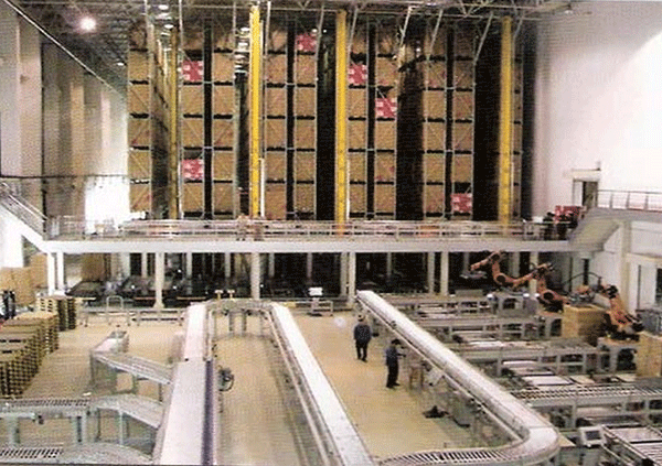
Warehouse Logistics
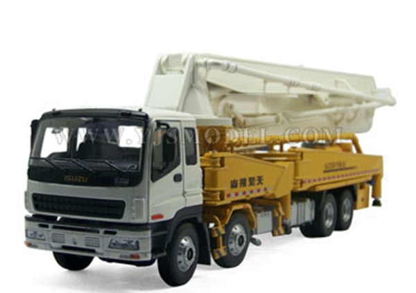
Construction machinery
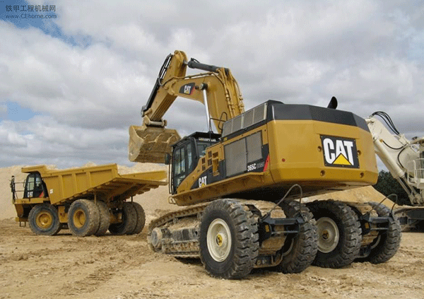
Construction machinery
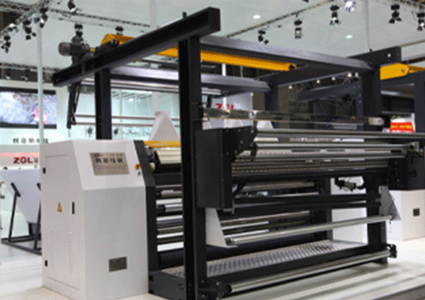
Textile machinery

Car transport

Escalator industry

Escalator industry
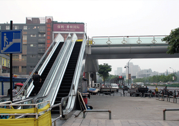
Escalator industry

Escalator industry
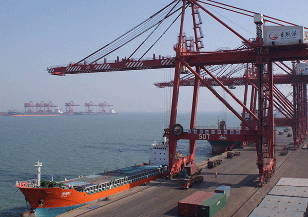
Port Machinery

Cement machinery

Environmental protection industry
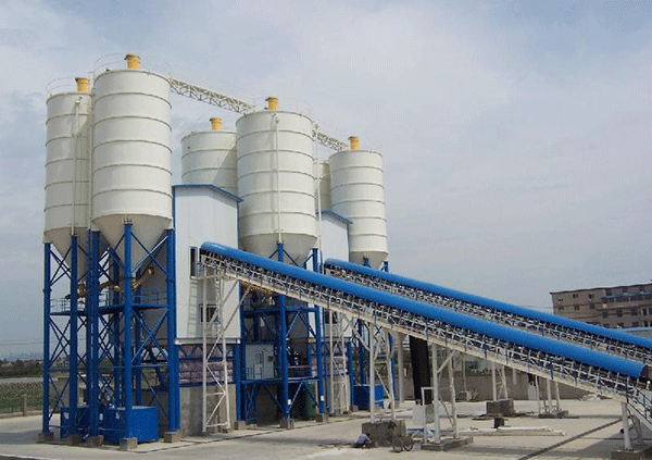
Construction machinery

new energy

Glass machinery

Communications industry

Stage machinery
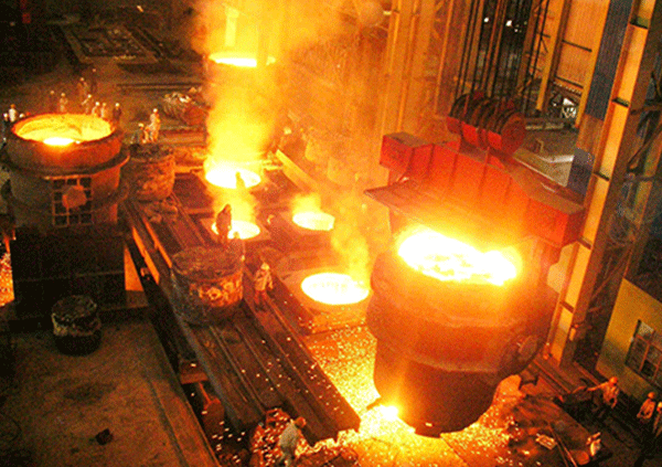
Metallurgical industry
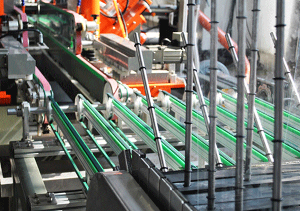
Glass machinery
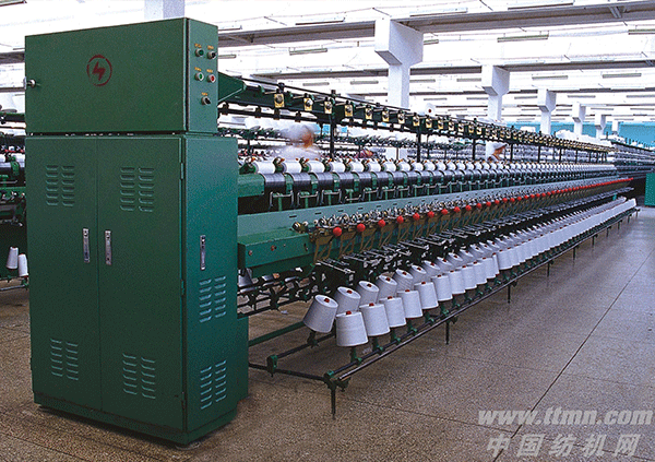
Textile machinery
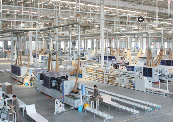
Woodworking machinery

Food Machinery

Warehouse Logistics
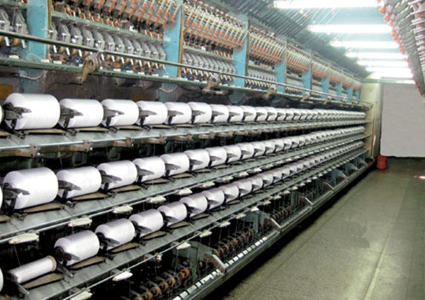
Chemical fiber industry

Environmental protection industry

Grain and oil machinery
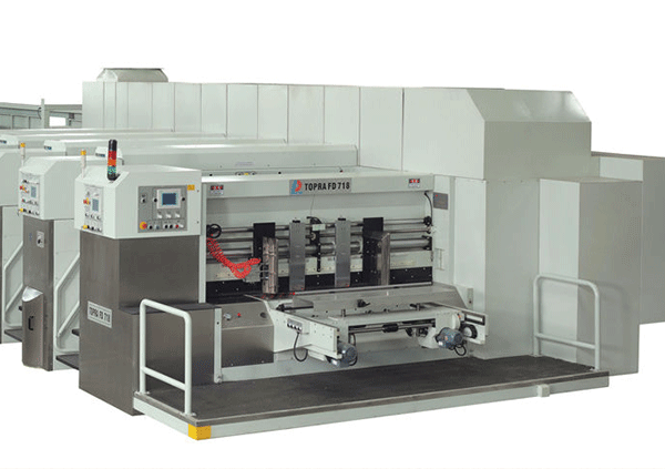
Packaging Machinery
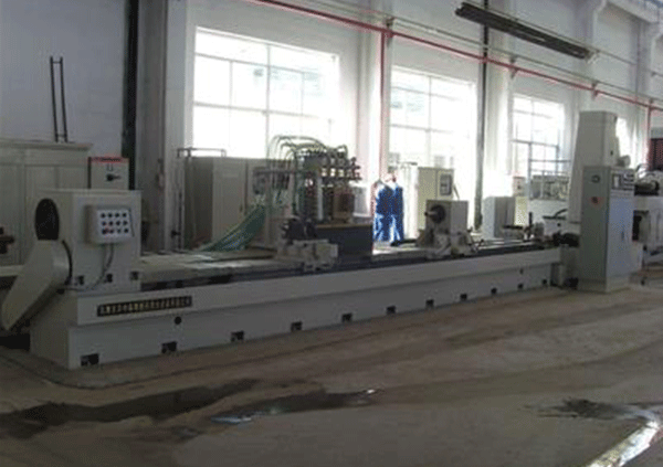
Grinding machine

Oilfield industry